

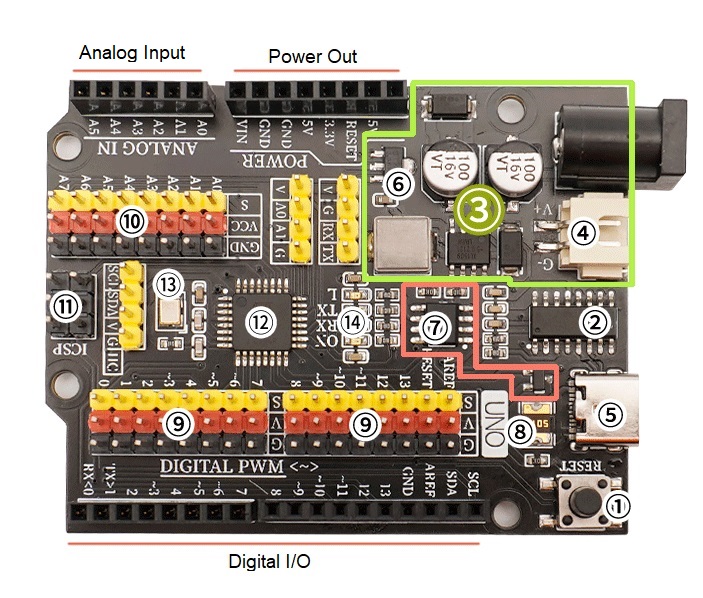
① Reset Button
Press the reset button to restart the program.
② USB-to-Serial Chip
This chip converts the data received from USB into serial data and sends it to the main control chip.
③ 5V/2A Power Supply Module
The power supply module provides power to the main board. It regulates an external 6–12V input to 5V/2A (10W) output, which can drive multiple servos, toy motors, micro linear sliders, and other devices.
④ 6–9V Battery Connector
A dedicated battery connector that can be connected to an AA battery holder or 18650 lithium battery pack. This makes the development board easier to arrange when building mobile projects.
⑤ USB Interface
Used for program downloading and USB power supply.
⑥ 3.3V Power Chip
Provides 3.3V voltage output for the development board.
⑦ Automatic Switching Controller for External Power and USB Power
An automatic power switching system composed of an FDN340P MOSFET and LMV358IDGKR amplifier.
By default, the development board is powered through the USB interface. When an external power supply is connected, the controller automatically disconnects USB power and switches to the external power source. When the external power is removed, it automatically switches back to USB power. This function protects the computer from interference caused by external power supplies connected to the development board.
⑧ Resettable Fuse
If a short circuit occurs due to incorrect wiring on the development board, the fuse automatically disconnects the circuit between the board and the computer, protecting the computer’s USB port from damage or system crashes.
⑨ Digital G | V | S Expansion Interface
The onboard digital G | V | S interface makes it easier and faster to connect sensors or actuators, eliminating the need for an expansion shield when building projects.
- G = GND (power negative)
- V = VCC (power positive)
- S = IO signal interface
The G/V pins provide 5V/2A output, meeting the power requirements of most sensors and actuators.
⑩ Analog G | V | S Expansion Interface
The onboard analog G | V | S expansion interface allows convenient connection of analog sensors. Additional A6 and A7 analog input pins are provided to support more sensors.
⑪ ICSP Serial Programming Interface
Used for writing the bootloader to the development board or for downloading programs using a compiler.
⑫ ATMEGA328P Main Controller Chip
The ATMEGA328P is the brain of the development board. It handles program storage, execution, computation, and signal input/output.
⑬ Crystal Oscillator
Provides the clock signal for the ATMEGA328P main controller chip.
⑭ LED Indicator Lights
The board includes four LED indicators:
- ON – Power indicator (lights up when power is on)
- RX / TX – Serial communication indicators (blink when serial data is transmitted or received)
- L – D13 pin indicator (lights up when the D13 signal is HIGH)