
Model: JF020-7X1T1M
To visit and download the full version of the user manual, please visit: Single Axis Stepper Motor Controller. The password will be sent along with the shipping package.
Quick Start
There are three connection terminals on the back. See Figure 1 below:
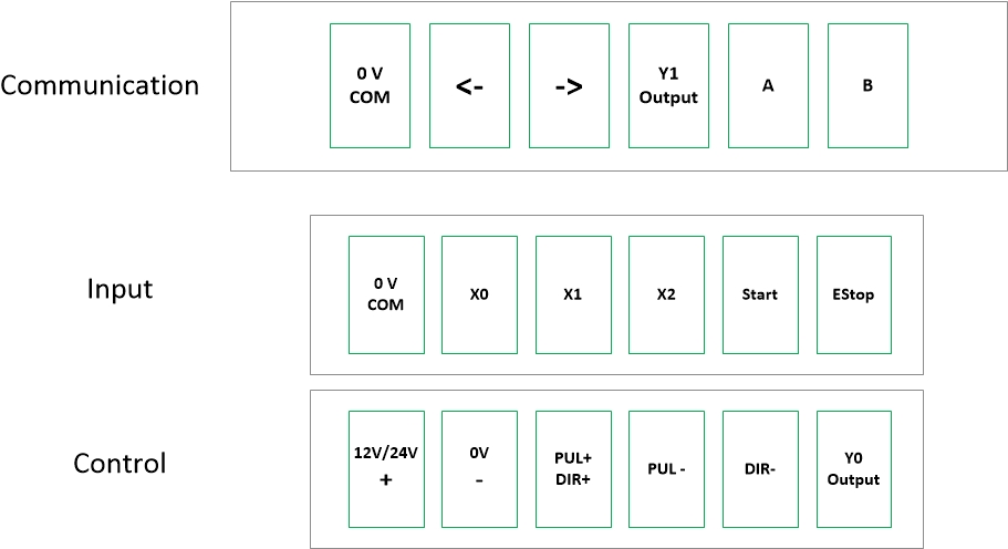
Figure 1
Communication Terminal.
(Optional) Used to communicate with other control device to manipulate this controller. The table below shows the function of each interface (from Left to Right):
| Port | Function |
| 1 | Common GRD for Port 2 and 3 |
| 2 | Left Move |
| 3 | Right Move |
| 4 | Y1 output. Used to show working status signal. |
| 5 | A, Used for Serial Communication. RX |
| 6 | B, Used for Serial Communication. TX. RX, TX should be switched for RS485 Device. |
Input Terminal.
(Optional) Used to connect with external limit switches, Start and Estop. The table below shows the function of each interface (from Left to Right):
| Port | Function |
| 1 | Common GRD for Port 2, 3, 4, 5, 6 |
| 2 | Sensor or limited Switch. Normal Closed. X0, Zero Point. |
| 3 | Sensor or limited Switch. Normal Closed. X1, Clockwise rotation Limit Switch |
| 4 | Sensor or limited Switch. Normal Closed. X2, Counterclockwise rotation Limit Switch |
| 5 | Start. Normal Closed. |
| 6 | Estop. Normal Closed. |
Control Terminal.
Used to connect with Power Supply and Stepper Motors. The table below shows the function of each interface (from Left to Right):
| Port | Function |
| 1 | 12V or 24V Positive |
| 2 | GRD |
| 3 | Connect to Stepper Motor Drive. Shared Positive for Pulse (PUL+) and Direction (DIR+) |
| 4 | Connect to Stepper Motor Drive. Pulse Negative (PUL- ) |
| 5 | Connect to Stepper Motor Drive. Direction Negative (DIR- ) |
| 6 | Y0 Output. |
Setup and Configuration
The front control panel has several control buttons. These buttons control the stepper motor’s operation as well as the controller’s configuration.
SET: Open, switch or exit the configuration menu. The choices will be displaced on the 6 digits of LED;
ENT: Enter. Enter the menu item;
LEFT: Run stepper motor in one direction;
RIGHT: Run stepper motor in another direction;
RUN: Start stepper motor based on the configuration;
STOP: Stop stepper motor.
MIN-MAX Knob: Control running speed or change value in the setup/configuration model.
There are two series of configurations that can be configured:
P (Parameter): Control how the panel’s button will be working
F (Function). Control the Pulse signal for stepper motor