
Welcome to select the LUNYEE Axis GRBL1.1 CNC Control Board. Please read the user manual before you start using it.
Disclaimer:
Please carefully read and comprehend the contents of this user manual. Failure to do so may result in injury, degraded results, or damage to the 4-Axis CNC Control board. It is essential to ensure that anyone using the 4-Axis GRBL Controller is familiar with and understands the manual’s contents.
The conditions or methods employed for the assembly, handling, storage, use, or disposal of the 4-Axis GRBL Controller are beyond our control and may exceed our knowledge. Consequently, we do not assume responsibility and explicitly disclaim liability for any losses, injuries, damages, or costs arising from or in any way related to the assembly, handling, storage, use, or disposal of the product.
While the information in this document is sourced from manufacture what we believe to be reliable, it is provided without any warranty, whether express or implied, as to its correctness. There is no warranty for open-source GRBL software described in the document. The entire risk regarding the quality and performance of GRBL rests with you.
In the Packages:
- Control Board x 1
- Type-C/USB Cable x 1
- XH2.54 Motor Cable x 1
- Mini Heatsink x 5
Wiring Diagram in PDF Format: 4 Axis GRBL Control Board Wiring:
Specification
| Processor Architecture: | ARM 32-bit |
| Firmware: | GRBL 1.1f |
| Driver Unit: | A4998 |
| Input Voltage: | DC 12~24V 5A |
| Current Specifications: | Standard 1.042A; Maximum: 2.083A |
| Software Support: | LaserGRBL, Lightburn, Candle, Universal G-Code Sender |
Wiring Diagram
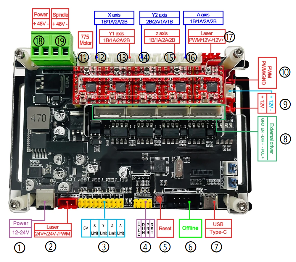
| Number in Diagram | Description | Optional Item |
| 1 | Input Voltage, 12~24V DC | DC Power Cable Male Connector 30cm Length Mean Well Switching Power Supply LRS-200 200W 24V DC Switching Power Supply |
| 2 | PWM output for 24V DC Laser Module (XH2.54 3Pin Plug). (Most of the laser module are using 12V DC PWM. Please ensure your laser module when using this port.). The output can also be regular 24 V output. | XH2.54 Male Connector Cable |
| 3 |
10 x 2 Pin Dupont Interface. Extra DC 5V output and X, Y, Z, A limit interface. X+ X-… pins are limit Pins |
Microswitch CNTD 10A |
| 4 | 8 Pin interface for Hold, Run, Probe and Reset switch. | CNC Z Axis Zero Setting Touch Probe Latching Push Button Switch with LED |
| 5 | Reset Button | |
| 6 | 8 Pin Offline Controller. | GRBL USB Driver Offline Controller with 1.8 inch LCD Screen |
| 7 | USB Type-C, Connect to USB Port in computer | |
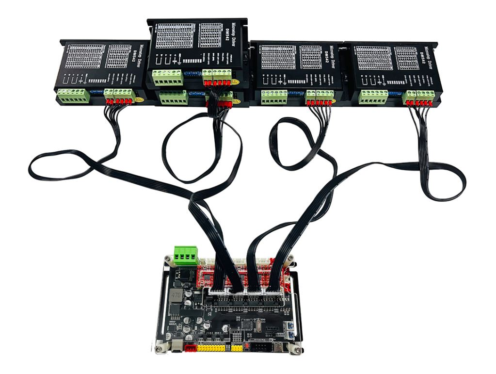
| 8 | 4 x 6pin XH2.54 Stepper Motor Driver Port. (To use these ports correctly, check your stepper moter driver manual). The 6Pin in order: ENA-, ENA+, DIR-,DIR+,PUL-,PUL+ | Stepper Motor Driver DM542 XH2.54 Male Connector Cable |
| 9 | XH2.54 Plug. 2 x 12V DC output. | |
| 10 | XH2.54 Plug. PWM output. Normally used with 9 for 2P+2P Laser Module | Laser Module with FAC C Lenses Fixed Focus |
| 11 | 2Pin Ports for 775 Motor (Spindle) | |
| 12,13,14,15,16 | 4 Pin Plug for X Axis, Y1 Axis, Y2 Axis, Z Axis and A Axis | NEMA 17 (42mm) Stepper Motor |
| 17 | PWM output for 12V DC Laser Module (XH2.54 3Pin Plug) | Laser Module with FAC C Lenses Fixed Focus |
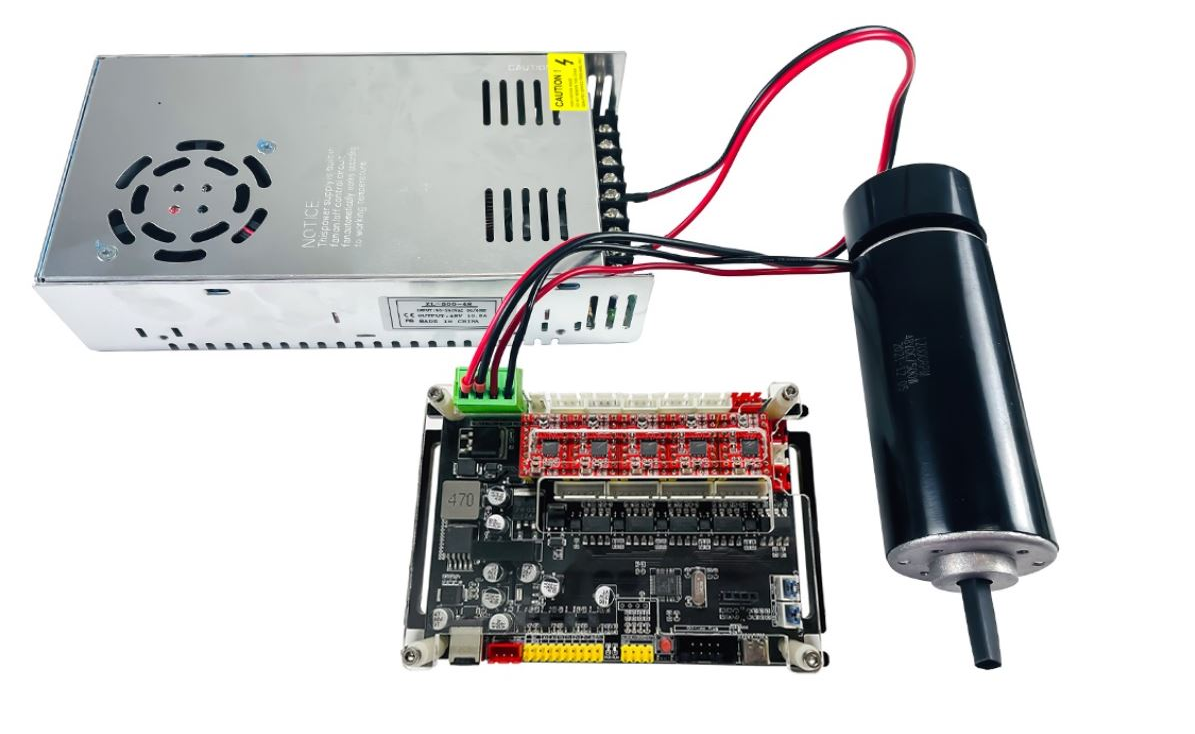
| 18 | 48V DC Input. Voltage source for stepper motor. Normally used with 19 together. Sample wiring see blow. | |
| 19 | 48V DC Stepper Motor. (Caution: Running a 48V stepper motor for an extended period may cause overheating. Additional cooling fan is recommended) | 48V DC Spindle Motor |
Operation Steps:
- Ensure all wires are connected properly
- Connect the board (Type-C) and computer (USB) using the USB Type-C cable
- Connect the board to DC Power (typically DC 24V)
- Make sure there is an emergency stop or proper power off switch to turn off the machine immediately in case of any issue.
- Make a backup of default GRBL setting. In the command line window of software, type $$ to get the default settings and save the result to your local file.
Verify the controller by software
There are multiple software choices to control the board. The sample below is using open source software Candle and UGS to verify the operation.
- Candle. The software can be downloaded here: https://github.com/Denvi/Candle (Version GRBL v1.1)
- Open Service -> Settings – > Connection, Refresh Port, the board connection port should be automatically appeared:
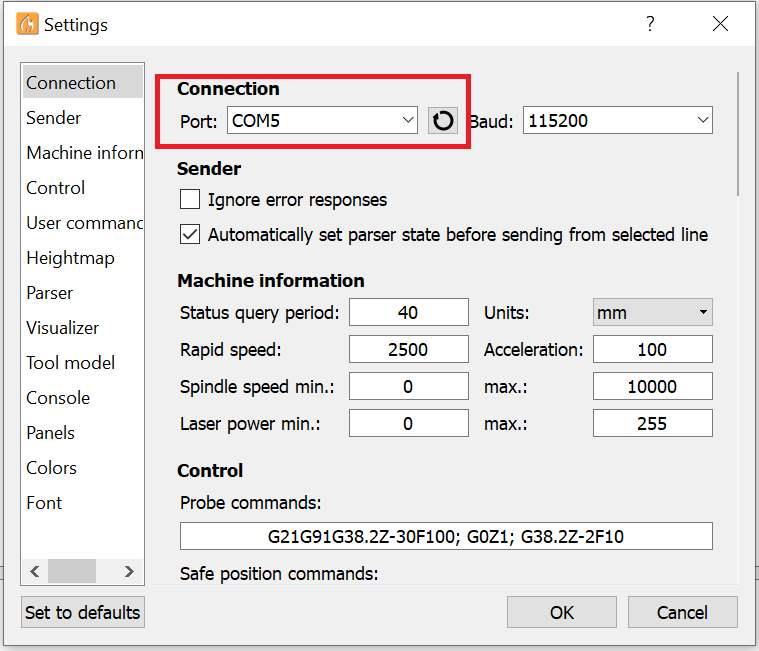
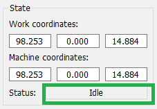
- The State panel will show the current status is Idle. which means your CNC is ready to use.
- Open Service -> Settings – > Connection, Refresh Port, the board connection port should be automatically appeared:
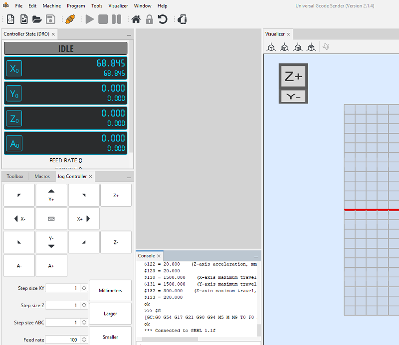
- Universal G-Code Sender (UGS). The software can be download from: https://winder.github.io/ugs_website/
- If the control board is connected to the computer correctly, the Port dropdown list should display control board name: LUNYEE_4axis_Control.
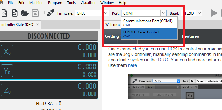
- Click the Connection icon from in the tool bar, the control board should be connected properly.
- If the control board is connected to the computer correctly, the Port dropdown list should display control board name: LUNYEE_4axis_Control.
Firmware Flashing
The control board has been upgraded to the latest version of GRBL 1.1f(2023). There is no need to flash the board at this moment, and users are advised against any unnecessary flashing, as it involves risks. However, if a new firmware release occurs within one year, we will provide guidance on flashing the firmware if necessary.
Reference
GRBL Setting G-Code document: https://github.com/gnea/grbl/tree/master/doc
Support
We consistently share our experiences on this page with our customers regarding the use of this controller. Please note that issues related to G-Code, software, etc., are not within our service scope. We may provide limited suggestions or references on these matters. If you have any questions, feel free to contact us at [email protected].
Manufacturer Default GRBL Configuration:
$0 = 6 (Step pulse time, microseconds)
$1 = 25 (Step idle delay, milliseconds)
$2 = 15 (Step pulse invert, mask)
$3 = 0 (Step direction invert, mask)
$4 = 0 (Invert step enable pin, boolean)
$5 = 0 (Invert limit pins, boolean)
$6 = 0 (Invert probe pin, boolean)
$10 = 1 (Status report options, mask)
$11 = 0.010 (Junction deviation, millimeters)
$12 = 0.002 (Arc tolerance, millimeters)
$13 = 0 (Report in inches, boolean)
$20 = 0 (Soft limits enable, boolean)
$21 = 1 (Hard limits enable, boolean)
$22 = 1 (Homing cycle enable, boolean)
$23 = 31 (Homing direction invert, mask)
$24 = 25.000 (Homing locate feed rate, mm/min)
$25 = 3500.000 (Homing search seek rate, mm/min)
$26 = 250 (Homing switch debounce delay, milliseconds)
$27 = 1.000 (Homing switch pull-off distance, millimeters)
$30 = 1000 (Maximum spindle speed, RPM)
$31 = 0 (Minimum spindle speed, RPM)
$32 = 0 (Laser-mode enable, boolean)
$33 = 0
$34 = 0
$35 = 0
$36 = 0
$37 = 0
$38 = 10
$39 = 0
$100 = 80.000 (X-axis travel resolution, step/mm)
$101 = 80.000 (Y-axis travel resolution, step/mm)
$102 = 800.000 (Z-axis travel resolution, step/mm)
$103 = 800.000
$110 = 20000.000 (X-axis maximum rate, mm/min)
$111 = 20000.000 (Y-axis maximum rate, mm/min)
$112 = 200.000 (Z-axis maximum rate, mm/min)
$113 = 200.000
$120 = 500.000 (X-axis acceleration, mm/sec^2)
$121 = 500.000 (Y-axis acceleration, mm/sec^2)
$122 = 20.000 (Z-axis acceleration, mm/sec^2)
$123 = 20.000
$130 = 1500.000 (X-axis maximum travel, millimeters)
$131 = 1500.000 (Y-axis maximum travel, millimeters)
$132 = 300.000 (Z-axis maximum travel, millimeters)
$133 = 280.000